
Packet Loss on Surveillance Radar Channels
Project Description
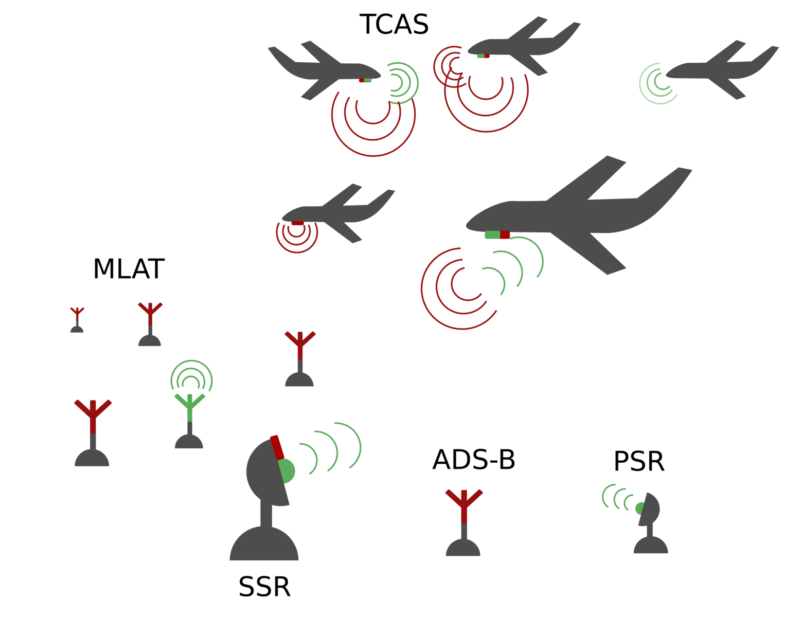
Civil aircraft surveillance is carried out on two radio channels at 1030 MHz and 1090 MHz. These channels are the same for all air spaces and commercial aircraft around the world. From the very beginning of aviation surveillance until now the number of aircraft and and applications has constantly grown while the compatibility to legacy protocols had to be maintained. Nowadays, most of the surveillance in civil aviation is ”cooperative” meaning that the aircraft is actively replying to surveillance equipment like radar stations. Most of the surveillance is carried out in a interrogation-reply pattern where a ground station is querying an aircraft for an position update. The very basic primary surveillance radar (PSR) sends out strong electromagnetic impulses and measures the roundtrip-time of the echo to calculate the distance between reflecting surface and radar antenna. However, this soon became unsuitable as one is neither able to calculate the altitude of a target nor to identify the aircraft. This led to the development of secondary surveillance radar (SSR) which sends out interrogations on 1030 MHz and queries any target to reply with either its altitude or its call-sign on 1090 MHz. This was later upgraded by Mode-S SSR that allowed the radar station to query a wide range of aircraft parameter and uses more sophisticated modulations. The newest surveillance technologies like Automatic Dependent Surveillance - Broadcast (ADS-B) and multilateral systems (MLAT) are developed to reduce interrogations on the 1030 MHz channel. Futhermore, the anti-collision system TCAS where each plane is querying its surrounding is also using the radar channels thereby adding even more channel load. This heterogeous communication structure is shown in the figure.
The more aircraft are in the air, the more data needs to be transmitted over the channels. New applications and a growing air traffic have led to a critically high occupancy of the channels. But until now no overall monitoring system is in place that is capable to constantly monitor these channels and to estimate the amount of lost packets due to collisions on the physical channel.
The aim of this research is to allow permanent monitoring within a large area in a cost effective yet precise and telling way. This is achieved by inspecting the channels on protocol layer and assuming physical disturbances by using software only.This knowledge is crucial in increasingly dense air spaces to ensure a reliable surveillance for air traffic control. This research proposes and evaluates parameters, available on the decoder-side of the receiver, which are suitable to estimate the channel load.
Estimation of Receiver Loss
In order to monitor the channel load, a standard ATS-receiver is used to decode the communication on the reply channel. To estimate the losses a small amount of artificial but valid packets is injected into the channel. The receiver is decoding the entire communication on the channel including the artificial test packets. By estimating the losses on the portion of test packets a machine learning aided software shall be able to extrapolate the loss rate to the entire channel thus, allowing a full estimation on all losses, regardless of type and amount of traffic for a specific channel load situation.If it turns out that there is a stable amount of channel situations (i.e. at least a weak-sense stationary process) the training packets might be removed after some time as the system has trained all situations that apply to this receiver in this environment. Special certainty factors could than be used to inspect a drift of the environment if the situation starts to change.
The use of a commercial off-the-shelf-receiver for a very essential part of the channel estimation has two major challenges:
- Homogeneous distortion behaviour for all packets: It must be investigated if the training samples suffer from the same distortions as the received packets from aircraft and the receiver has the same probability to decode sample and real packets. As the system will only get information from the loss-rate of the training samples this is crucial in order to gain knowledge of the receivers behaviour for all types of packets on the input-side.
- Singularity of RF-situations: The system must be able to distinguish between receiver behaviour and RF-situations on the input site. The data-set must therefore consist of a very broad set of parameters to create a unique fingerprint of all situations on the input side of the receiver. For example: One must be able to find a difference between a low rate of packets on the output side caused by a low packet rate on the input (i.e. few aircrafts around the receiver) and low number of packets due to high distortions on the input side (i.e. over-crowded environment). An indication of distortions could be a shift of all decodable packets to higher RF-levels or a shift to shorter packets that have a higher chance for undisturbed transmissions.
These assumptions need to be proofed in this research in order to follow the outlined approach. Finally all relevant parameters and metrics must be defined in a way that future measurement systems will be able to reference to them and by this to create comparable results between different measurement systems.
Channel Loss Estimation
The estimation of the entire channel is done in 3 stages as shown in the figure below. First the full channel is simulated using two software defined radios. One software defined radio (SDR) is sending test packets of a certain type and level to the receiver. In parallel, a second SDR is simulating traffic on the channel with a known amount of packet and disturbances. A software on the output is counting the successfully decoded test packets and estimates the loss rate for this particular type. In this setup the software tries to estimate the total amount of packets that where sent beforehand. As the number of simulated packets is known the quality of the estimation can easily be assessed. In a second stage the injection of the test packets is applied to a real world channel (i.e. an antenna is attached to the receiver). The packets amount is unknown to the software, and only the losses of the test packets can be used to estimate the entire channel loss.
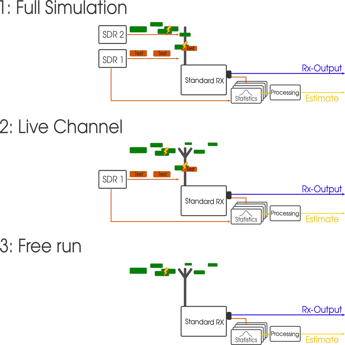
Finally, the software should be able to estimate the channel losses without the injection of test packets. This could be achieved by a ML solution that is able to distinguish between equal looking channel loads by the constellation of packet types and levels. In order to do this, the system needs to be trained with a wide range of data thereby learning the receiver’s behaviour for this particular setup.
Contact
Communication
Birkenweg 8
64295 Darmstadt
Office: D16, 210
Communication
Birkenweg 8
64295 Darmstadt
Office: D16, 210
Contact for this project
For further information regarding this project please contact Roman Raekow.